With release v4.1 software of the Ethernet Routing Switch 8600 Nortel introduced a new mechanism to protect against Layer 2 network loops. The following excerpt is taken from the Nortel document “Converged Campus Technical Solution Guide”, authored July 2007 by Dan DeBacker.
Simple Loop Prevention Protocol (SLPP) provides active protection against Layer 2 network loops on a per-VLAN basis. SLPP uses a lightweight hello packet mechanism to detect network loops. SLPP packets are sent using Layer 2 multicast and a switch will only look at its own SLPP packets or at its peer SLPP packets. It will ignore SLPP packets from other parts of the network. Sending hello packets on a per VLAN basis allows SLPP to detect VLAN based network loops for un-tagged as well as tagged IEEE 802.1Q VLAN link configurations. Once a loop is detected, the port is shutdown. The SLPP functionality is configured using the following criteria:
- SLPP TX Process – the network administrator decides on which VLANs a switch should send SLPP hello packets. The packets are then replicated out all ports which are members of the SLPP-enabled VLAN. It is recommended to enable SLPP on all VLANs.
- SLPP RX Process – the network administrator decides on which ports the switch should act when receiving an SLPP packet that is sent by the same switch or by its SMLT peer. You should enable this process only on Access SMLT/SLT ports and never on IST ports or Core SMLT/SLT ports in the case of a square/full mesh core design.
- SLPP Action – the action operationally disables the ports receiving the SLPP packet. The administrator can also tune the network failure behavior by choosing how many SLPP packets need to be received before a switch starts taking an action. These values need to be staggered to avoid edge switch isolation – see the recommendations at the end of this section.
Loops can be introduced into the network in many ways. One way is through the loss of an MLT configuration caused by user error or malfunctioning equipment. This scenario may not always introduce a broadcast storm, but because all MAC addresses are learned through the looping ports, does significantly impact Layer 2 MAC learning. Spanning Tree would not in all cases be able to detect such a configuration issue, whereas SLPP reacts and disables the malfunctioning links, limiting network impact to a minimum. The desire is to prevent a loop from causing network problems while also attempting to not totally isolate the edge where the loop was detected. Total edge closet isolation is the last resort in order to protect the rest of the network from the loop. With this in mind, the concept of an S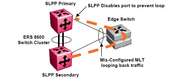 LPP Primary switch and SLPP Secondary switch has been adopted. These are strictly design terms and are not configuration parameters. The Rx thresholds are staggered between the primary and secondary switch, therefore the primary switch will disable an uplink immediately upon a loop occurring. If this resolves the loop issue, the edge closet still has connectivity back through the SLPP secondary switch. If the loop is not resolved, the SLPP secondary switch will disable the uplink and isolate the closet to protect the rest of the network from the loop.
I’ve deployed SLPP at one site with with a two tier network design utilizing SMLT with an IST core. It’s very important to remember that SLPP operates per VLAN id so you need to take that into consideration. You also don’t want to overload your switch fabric (CPU) by enabling SLPP on every VLAN, especially if you have a large number of VLANs.
Here’s an example of how to deploy SLPP between two core ERS 8600s (switch cluster).
ERS 8600 Core Switch A
ERS-8610:5# config slpp add 200
ERS-8610:5# config slpp operation enable
ERS-8610:5# config ethernet 1/1-1/8 slpp packet-rx enable
ERS-8610:5# config ethernet 1/1-1/8 slpp packet-rx-threshold 5
ERS 8600 Core Switch B
ERS-8610:5# config slpp add 200
ERS-8610:5# config slpp operation enable
ERS-8610:5# config ethernet 1/1-1/8 slpp packet-rx enable
ERS-8610:5# config ethernet 1/1-1/8 slpp packet-rx-threshold 50
This will cause both core ERS 8600 switches to transmit SLPP PDUs on VLAN 200. They will watch for those PDUs to return on port 1/1-1/8. It’s important in the example above to point out the different thresholds. You don’t want both core ERS 8600 switches cutting off both uplinks to the edge closets. Hence the core A switch will admin-down any port where it receives 5 of it’s own SLPP PDU packets. The core B switch will admin-down any port where it receives 50 of it’s own SLPP PDU packets. This configuration will generally disable one of the uplinks from the switch cluster (removing the loop) but won’t leave the edge switch disconnected from both core ERS 8600 switches.
Cheers!
Michael,
We had 3 problems last year with different communication closets that contain 470 stacks. Each instance was a little different, but 2 of the 3 introduced a loop on our network. SLPP isn’t yet implemented, but I’m looking at doing it this year.
To get out of the loop right away, we obviously had to disconnect the link from the failed (rather semi-failed) 470 unit that had one of the uplinks to the core 8600’s, then replace the unit. It’s best when the damn 470’s just fail hard, but when they choke along and lose their MLT config and such, it can be hell on the network.
You mention you’re at a very large healhcare site, I’m just curious, is SLPP implemented for all of your communication closets? Why not implement everywhere, I know you mention it is per VLAN, but if one of those VLAN’s (i.e. default VLAN1) is part of all of the uplink’s, you technically would only have to implement for that one VLAN right, even though you have others configured, the 8600’s would still shutdown the ports correct?
One other question, what is the best way to test an SLPP configuration….manually break an MLT trunk while it is connected? Since I’m in a production environment and creating a loop wreaks havoc on our network/systems in the worse possible way (lots of automation systems here running 24×7) I’m looking for some advice other than site-wide downtime. :)
Thanks!
Greg
Hi Greg,
In the past we’ve had quite a few different problems that caused a loop in our local area network. Over the years though we’ve developed procedures and configuration templates that help to mitigate any such problem from actually taking down the entire local area network. I should probably point out that we’re always refining these procedures and configuration templates – sometimes to incorporate new features and sometimes to tweak our approach when we learn something new and valuable.
I hope to make a more detailed post in the future to discuss just how to best configure the network to protect against some of the problems you mentioned above. In the short term let me try to answer some of your questions and points that you made above. As a last resort we utilize the CP-LIMIT feature of the ERS 8600 switch to disconnect any uplink/downlink which exceeds a specified number of broadcast/multicast packets per second. I’m currently using values of 5,000 and 7,500 for broadcast and multicast respectively. The ERS 8600 switch will automatically disconnect (it doesn’t actually admin-down the interface so it can be confusing when you start your initial troubleshooting – you can determine if the interface was shutdown because of CP-LIMIT by examining the logs) any interface that exceeds packets per second configuration thereby isolating the affected switch but preserving the core network. The CP-LIMIT feature protects the CPU because broadcast/multicast traffic must be processed by the CPU which could lead to an unresponsive switch if too many broadcast/multicast packets start to hit the CPU.
I haven’t implement SLPP everywhere yet because I have not yet completed a migration from DMLT to SMLT. Once the SMLT migration is complete we will definitely be deploying SLPP along with VLACP.
Which VLANs should you enable SLPP in? You need to remember that you can inflict a loop in a single VLAN as opposed to an entire 802.1q tagged uplink/downlink. I run SLPP in all my closet VLANs, management VLAN and the major application VLANs such as our PACS VLAN.
We also utilize Spanning Tree on every switch/stack to help prevent any loops between the ports on the switch/stack. We disable Spanning Tree on any uplinks out of the closet (we don’t run Spanning Tree between the closets and the core – only locally within each closet). We’ve also enabled rate limiting to help contain any loops that might still be inflicted. You’ll still have ARP/FDB issues due to the loop but it should prevent a complete shutdown of the affected switches allowing you time to locate and disconnect the offending device.
You could test by simply disabling the MLT on the edge switch.
I would strongly advise that you have console access to both ERS 8600 switches so you can watch the CPU utilization (show sys perf) and disable the downlinks should things not work as expected.
Thanks for the comment and good luck!
Hi Guys,
It should be noted that SLPP was developed specifically to operate with SMLT topologies, they’re maybe advantages to the protocol in other topologies but it was design specifically to operate with SMLT.
You can interestingly achieve very similiar SLPP functionality with the existing CP-limit feature in SMLT topologies. By creating a dummy non-data vlan on the two core 8600 switches and then interconnecting the vlan using a NON-IST link. VRRP is then enabled on the vlan to generate traffic on the vlan. The vlan in then created on all the edge switch with MLT (tagged) connection to the two core SMLT switches. As the edge is connected via MLT their won’t be an physical loop in the network so no problem.
If a switch on edge stack fails or a the MLT is missconfigured, a physical loop will be created in the dummy vlan, causing the VRRP packets to loop. The VRRP packets looping will cause the CPU-limit to kickin and shutdown the effected port and therefore breaking the physical loop caused by the edge switch. This functionality is the origion of the SLPP protocl
Cheers
and on the edge swithc
Thanks for the information!
Michael,
normally, the case with edge –> core SMLT uplinks is to disable STG at the edge uplink ports (optional…but on the 8600 it is required for SLT/SMLT ports)…i have generally kept STG enabled at the edge uplink ports in case there is an issue at the core (SMLT configuration lost on the 8600s, and with STG disabled on both sides, a loop will occur). this can also happen if there is SLPP config loss at the same time on the 8600s. What do you think about this approach? You have SLPP to correct MLT configuration loss at the edge, but what is there to correct SMLT configuration loss (or any other issue on the downlink ports) so that you don’t have a loop going from edge –> core? this is generally why i keep STG enabled on the edge uplink ports as a further backup.
most of these protocols seem to be for protecting a MLT config loss at the edge, but maybe not necessarily a mishap at the core side? what are your thoughts about this?
also, I’m curious to learn more about the comment above (and i came to the same conclusion myself as i am reading on SLPP), about just enabling SLPP on VLAN 1 (since that is configured on all trunk ports in the campus, even though it is essentially a dead VLAN with no traffic). does anyone have any experience with running SLPP on just VLAN 1?
and to confirm one last thing as i am researching this to test in lab and eventually put into production…SLPP should -only- be enabled on downstream ports that are SLT or SMLT. They -should not- be enabled on IST ports, or SMLT ports that go to another IST set of 8600s (as in a square/full-mesh design).
Thanks! stumbled across your blog recently, and will certainly be engaged in more conversation…
-Michael Gagnon
only do on smlt, NOT any IST ports or SMLT to other 8600 IST groups (square full mesh)
Hi Michael,
I’m not sure I’ll get to all your points tonight but let me take a first stab.
I’m not completely understanding why you want to “protect” the edge. In my environments if the edge switches get disconnected from the core backbone the network is useless to those folks. Yes the local edge switch might be up but all the applications including voice and data are only reachable through the core backbone.
If STP is disabled on your core uplinks but enabled on the edge downlinks I don’t think you’ll protect your edge switch like you think. With STP enabled globally on the core but disabled on the uplinks it will not forward BPDUs that come from your edge switch. Have you tested your approach? I think you’ll find that it doesn’t work and you think it should and probably doesn’t buy you anything.
Assuming there is a mis-configuration at the core or someone wires the fiber uplinks to the wrong ports CP-LIMIT will still protect your core backbone from too much traffic flooding in the event of a loop. CP-LIMIT is a last ditch effort to protect the core backbone. SLPP helps by trying to isolate an uplink should the SMLT/MLT connection itself be creating the loop (edge switch gets set to factory defaults – yes we’ve had it happen).
We actually have found that rate-limiting on the edge switches helps to keep the network from entirely collapsing. As a standard we now set all edge switches to rate-limit all Multicast and Broadcast traffic at 5% of the link speed.
The idea behind all of this is to protect the core backbone even if you have to sacrifice an edge switch.
With regard to your question about running SLPP in a square/full mesh configuration I will ask the powers that be and let you know. I’m only running SLPP at one campus right now but I am running it in all my closet VLANs and in my management VLAN.
Thanks for your comment!
ah, i see…STG disabled at the core edge ports wouldn’t forward BPDUs from the edge (STG enabled on the edge switch uplink ports just as a pre-caution), so it really doesn’t add any layer of protection.
Hello
I have a customer expericing loops in their network due to student and staff intervention. We have CP-limit turned on so that when the ports see a broadcast storm the ports are shutdown. I would like to know what do i gain, if anything by turning SLPP and cp-limit at the same time.
Hi Kenny,
I would advise that you look at the following measures to help protect your network;
– Spanning Tree Protocol with FastStart on all edge ports (you could also run MSTP or RSTP if you prefer that)
– If you are using Nortel edge switches configure rate limiting to help keep the loop from crushing your network
– If you are using rate limiting adjust your CP-LIMIT values down so CP-LIMIT can detect the problem and isolate the offending closet.
After you’ve setup all that you should also enable SLPP to protect against a problem with the edge MultiLink Trunk (MLT) configuration.
In all honesty we’ve found that Spanning Tree will help isolate 99% of the problems that involve end users and/or field engineers. Although you don’t want to run Spanning Tree on your uplink ports… make sure those ports are disabled. The rate limiting feature helps to keep a loop from initially bringing down your entire network, although you’ll still experience ARP/FDB corruption issues but you’ll at least get some time to locate the problem and resolve it before everything comes crashing to a halt.
If you are using Nortel for your edge switches you might be interested in looking at this article;
http://blog.michaelfmcnamara.com/2007/10/nortel-ers-5520-pwr-switch/
Good Luck!
Hi Michael,
We have implemented SLPP in approx. 10 VLANs. We are very positive about this mechanism and therefore want to deploy SLPP over more VLANs (60 at this moment). You are saying not to deploy SLPP over too many VLANs since it uses CPU resources. Can you tell me in how many VLANs you are using SLPP? Would SLPP behave well when deployed in 100 to 200 VLANs?
Thanks,
Ata
Hi Ata,
In my opinion there’s no need to run SLPP in every VLAN.. it would be very inefficient to-do so and serve almost no purpose. You only need to run SLPP in the those VLANs that cover the majority of your closets switch (uplink). In my case I have a location that has 11 closets. I run SLPP in the management VLAN (the VLAN where the IP addresses of all the equipment resides) along with the closet VLANs (each closet has it’s own VLAN and IP network). There are probably about 30 VLANs in all at this location but I know that every closet has at least one VLAN that has SLPP running on it.
Here’s what Nortel has to say with respect to SLPP;
This functionality provides active protection against network loops by sending out test packets and detecting self originated packets. It can be used in Spanning Tree networks as well as SMLT networks. Beginning with Software Release 4.1 Nortel recommends using SLPP to protect the network against L2 loops. In addition, the extended CP-limit functionality can be put into place to protect against DOS attacks where required. For earlier releases please refer to the corresponding release notes.
Loops can be introduced into the network in many ways. One way is through the loss of an MLT configuration caused by user error or malfunctioning as shown in Figure 32. This scenario does not introduce a broadcast storm, but because all MAC addresses are learned through the looping ports, does significantly impacts L2 MAC learning. Spanning Tree would not in all cases be able to detect such a configuration issue, whereas SLPP reacts and disables the malfunctioning links, limiting network impact to a minimum.
It’s really designed to protect you against a misconfigured or malfunctioning MultiLink trunk on the edge switch.
Cheers!
Michael,
I am planning to implement SLPP only in the business critical VLANs (these are VLANs that cover many uplinks). For (s)MLT misconfiguration you need to send SLPP in only one VLAN. The reason why i want to deploy SLPP in business criticall VLANs is for loop prevention on access port, in case of misconfiguration or malfunction (STP not configured of not working properly).
I think that if SLPP wants to be a good alternative for Loop Detect, it should be possible to enable it on large amount of VLANs.
From Nortel we got the information that SLPP had been tested in 40 VLANs and that this was not a problem. Now the question is, what happens when you go to 100 VLANs or above?
Cheers,
Ata
Thanks for the feedback Ata!
Good Luck!
Hi,
I have a problem with slpp.
I have the same vlan for 3 different smlt, and i’m receiving slpp frames on one of the smlts with a 3 day interval.
What can be the problem?
Regards,
LR
Hi Luis,
What version of software are you running? I’m assuming your using Ethernet Routing Switch 8600s and not the 5000 series?
Assuming that the software release is fine, no bugs or known issues I would suspect the possibility of a brief loop within the specific switch/stack that connects to the offending port.
Have you checked the configuration of every port and every device that connects to the switch/stack that is having issues? I would advise you make sure you have Spanning Tree enabled on all edge ports within that switch/stack. You might also want to enable BPDU guard to help keep any un-authorized switches from being connected downstream which could then cause a loop depending on the scenario. For those that are following the thread here’s a quick example of the SLPP messages that the ERS8600 switch will generate;
CPU6 [12/18/08 07:38:09] SW WARNING slppRx: SLPP packet received Rx-Vlan 12, Rx-Port 1/3, PDU-Vlan 12, SRC-Mac 00:15:e8:a8:00:0c
CPU6 [12/18/08 07:38:09] SNMP INFO Link Down(1/3) due to slpp
CPU6 [12/18/08 07:38:09] SNMP INFO Slpp port down(SlppRxPort = 66, SlppRxVlan =12, SlppIncomingVlanId = 12, SlppSrcMacAddress = 00:15:e8:a8:00:0c)
What do the logs from the edge switch indicate when you correlate the events in the core?
Please feel free to post the logs from both the core switch and the edge switch over in the forums and I’ll try to follow-up for you.
http://forums.networkinfrastructure.info/nortel-ethernet-switching/
Cheers!
Michael, here is my scenario:
I have 2 5530 as Core Switches. Each pair of fiber port, goes to a stack of 4550T (from 2 to 4 switches stack) on each floor of the building. Each stack has (via MLT) two fiber conections with the 5530. One to the top switch, another one to the correspondent port in the bottom switch. So, ports 1/19 and 2/19, goes to 2 fiber ports on stack on floor 2, 1/20 and 2/20 goes to the stack in floor 3, and so on.
My question is, due this configuration, is it worth to enable SLPP to avoid Loops, or enabling STP on access ports and disabling it on trunks (fiber) ports will do?
Also, how do i handle ports that have ip phone 2002 and 2004, with are tagged, because i send voice to one vlan, and data to another? this ports needs to be trunk port in the switch. Disable STP as well?
Hi Dan,
Let me ask and then answer a simple question that should help explain SLPP;
Q. How will SLPP (Simple Loop Protection Protocol) save your network?
A. It will save you if you have an edge switch that boots with a default factory configuration where there is no MLT configured (can you say loop).
It will save you if you configure the MLT but forget to enable the MLT (don’t laugh it’s been done too many times).
It won’t save you from someone mistakenly looping two ports in the closet, you’ll need to rely on other features (BPDU guard, STP) to save you there.
How do you handle IP telephony? Well there are literally dozens of articles on this blog for you to peruse. I would start with this one that details a best practice configuration when configuring an edge switch. The commands have only been tested on a 5520 series switch but they should probably work with the 4500 series and I believe ADAC/LLDP-MED is now supported on the 4500 series switches (the 5520 was the only switch for a long time that support ADAC/LLDP-MED).
http://blog.michaelfmcnamara.com/2007/10/nortel-ers-5520-pwr-switch/
Spanning Tree should be set to FastStart on all edge ports and disabled on any uplinks/downlinks. You still need Spanning Tree enabled even if the port is connecting to an IP phone because you can still get a loop from an IP phone with the built-in PC port on the back of the phone.
I won’t go on to far… I’ve gotten off-topic already with respect to SLPP. If you have any other questions please post in the forums and I’ll be sure to follow-up with you. http://forums.networkinfrastructure.info/nortel-ethernet-switching/
Cheers!
Hi Michael,
I have two 8600s connected via IST, and upon late I have ports shutdown from with the following Error code :
CPU WARNING Shutdown port 2/19 due to excessive control frames multicast 0, broadcast 11201 packet per second
We have 4 ports configured in a SMLT trunk, two links to each 8600, and all four ports are being closed with the above message.
I disable and reenable the ports, and all is well again. The ports get shutdown over random days long periods.
Now, I am considering implementing SLPP to assist in this issue. But reading an above entry of yours about VLANs, my network is subnetted to each switch stack, without a single management VLAN per se, and switch IPs are resident in their applicable subnet.
I have about 80 or so VLANs on site, and I am curious about the number of VLANs associated with SLPP, and is there any other limitiations, I should be aware of?
Thanks in advance.
Regards
Ryan
Hi Ryan,
It would appear that CP-LIMIT is kicking in and shutting down the links in question because they are flooding too many broadcast frames into the core network. Just to be upfront with you 11,201 pps is a LOT of broadcast traffic. The default value for CP-LIMIT is 10000, however, I personally use 5,000 in my network.
I haven’t used SLPP in more than 10 VLANs at any one site because I generally only enable it on a few larger VLANs. I’d recommend you review the design guidelines to see if there are any hard/soft limits.
With respect to your symptoms, there is definitely something wrong somewhere. Perhaps it’s an operational bug in the software or perhaps it’s mis-configuration or perhaps a cabling issue (loop) or a mis-behaving device.
I would start with the basics and make sure your edge switch has a good configuration. You should confirm that the MLT trunk on the edge switch is configured properly (and ENABLED). You should also enable rate-limiting and confirm that STP is enabled on all edge ports. Assuming your configuration is good we need to look at either a software issue or a potentially mis-behaving device on the network.
What model edge switches are you using?
What version of software are they running?
Are you doing any IGMP/Multicast?
I believe I remember reading a blurb in some release notes about an issue with a broadcast storm emanating from an edge switch although I believe it had something to-do with Multicast traffic.
Good Luck!
Hi Michael,
Thanks for the prompt and informative response to my query.
The 8600s are ERS-8610 (5.1.1.1) but we have not yet enabled VRFs, with the smlts connected to 5530-24FTD, (FW:6.0.0.6 SW:v6.1.0.006), with access switches being 470s, with STG enabled on all ports except for their uplinks.
I don’t believe it is a loop or malfunctioning device, as the broadcast storms should not stop once a disable/re-enable the SMLT ports, but should continue to swamp the network, unless the SMLT ports are the loop itself.
Please correct me on by above logic.
We do have Multicast traffic, but the log entry defines it as broadcast.
We run a (Management of a sort) VLAN between the 8600s and 5530s over the SMLT, which is unique to that device’s SMLT.
I could enable SLPP just on that VLAN, and not on all the user VLANs that are spanned over that SMLT.
I have checked the SMLT configuration, but that has been stable for over a year up until now that is.
My CP Limit is 10 000, but I am about to enable rate limiting for multi and broad traffic.
Thanks once again
Ryan
Hi Ryan,
I’ve seen broadcast storms come and go without explanation. Sometimes it can be a user that creates the problem, and then when the network stops working they unplug and move on, clueless of the chaos they’ve left behind.
The reason I ask about Multicast is because there were a few known issues with 6.1.x were Multicast traffic get’s looped in the switch. I believe there is reference to a fix in 6.1.4 software similar to the following;
Under certain conditions, broadcast traffic looped into the stack could generate a broadcast storm (Q02162104).
You might want to try upgrading the switches to 6.1.4 software and see if that resolves the problem.
Just so I understand your topology, you are using the ERS 5530 switches as distribution switches which feed your edge 470s? So your edge 470s are MLT connected to a single ERS 5530 or are you also running the Advanced License with an IST/SMLT configuration on the ERS 5530.
That’s definitely an odd problem… but a good think that CP-LIMIT is kicking in and isolating the affecting switches or else your entire network might go down. Perhaps you could perform a port mirror of one of the SMLT uplinks out to a desktop/laptop with a continuous packet trace running. Might help you being able to go back and look at the broadcast frames. Perhaps the source MAC might provide some clue to the problem.
Good Luck!
Hi,
Thanks for looking in to the issue.
While we polling the 8600 by SNMP the “show sys perf” command shows 100% for a long time (couple minutes)
Log file contains:
CPU5 [11/06/11 17:09:44] SNMP INFO Slpp port down(SlppRxPort = 82, SlppRxVlan =140, SlppIncomingVlanId = 140, SlppSrcMacAddress = 00:e0:7b:88:aa:0c)
CPU5 [11/06/11 17:09:44] SNMP INFO Port 1/19 is an access port
CPU5 [11/06/11 17:09:44] SNMP INFO Link Down(1/19) due to slpp
CPU5 [11/06/11 17:09:44] SW WARNING slppRx: SLPP packet received Rx-Vlan 140, Rx-Port 1/19, PDU-Vlan 140, SRC-Mac 00:e0:7b:88:aa:0c
CPU5 [11/06/11 17:07:03] SNMP INFO Port 1/19 is an access port
CPU5 [11/06/11 17:07:03] SNMP INFO Link Up(1/19)
CPU5 [11/06/11 16:59:33] SNMP INFO Slpp port down(SlppRxPort = 82, SlppRxVlan =140, SlppIncomingVlanId = 140, SlppSrcMacAddress = 00:e0:7b:88:aa:0c)
CPU5 [11/06/11 16:59:32] SNMP INFO Port 1/19 is an access port
CPU5 [11/06/11 16:59:32] SNMP INFO Link Down(1/19) due to slpp
CPU5 [11/06/11 16:59:32] SW WARNING slppRx: SLPP packet received Rx-Vlan 140, Rx-Port 1/19, PDU-Vlan 140, SRC-Mac 00:e0:7b:88:aa:0c
CPU5 [11/06/11 16:56:05] SW INFO user rwa connected from 129.2.70.53 via telnet
CPU5 [11/06/11 16:55:44] SW INFO Closed telnet connection from 129.2.70.53, user rw rcmd -2
It seems that a loop is creating in the network and it raises the cpu util high.
There is no SMLT created in the network but then also user has enabled SLPP on the ports.(not recommended).
Can you please suggest me what action should be taken to resolve the issue.
Regards
Ronit
I believe I replied to your thread in the forums.
http://forums.networkinfrastructure.info/nortel-ethernet-switching/slpp-brought-trunk-down/
Cheers!
Hello Michael,
Great post.
I’m really new in the Avaya world.
I have some question about implementation of Slpp :
– SLPP must be enabled only on the Core Switches or also on access switches attached via smlt ?
– We must disable STP on the core switches ports only or also on the access switch port facing it ?
Cheers.
Philippe
Hi Philippe,
You typically only run SLPP on your core switches – not on the edge switches.
You disable STP on the uplinks (on the edge) and the downlinks (on the core). You should still run STP on all the edge ports (user ports) to prevent any accidental loops between ports.
If you have additional questions I would suggest dropping by the forums;
http://forums.networkinfrastructure.info/nortel-ethernet-switching/
Cheers!
Hi Michael,
I have Two switch 8610 and they have a MLT trunk between them in order to forward a VLAN for the voice. They ‘re connected each of them by a simple link to a third’s switch. I don’t have the rights on this switch but i want to be sure to avoid any switching loops. What is the best solution ? In this case , SLPP is it the best solution i have ?
Thanks for your help !
Just an another information, the 2 “simple links” are trunking the same vlan to the two other switchs (8610)
You should use SLPP in combination with cp-limit.
Cheers!
Hi Micheal,
i am asked to write a project on DEALING WITH LOOPS IN MODERN COMMUNICATION TECHNOLOGY.Could you please help me out with some materials? i’l really appreciate it if you assist me,thanks
hi Mike, thanks for this post!!
can you please explain me what is the difference between SLPP-Guard and SLPP enable on per interface? also, if i enable SLPP per interface (not globally) does it going to work? and what happened if i just enable SLPP globally (not per vlan or per interface )