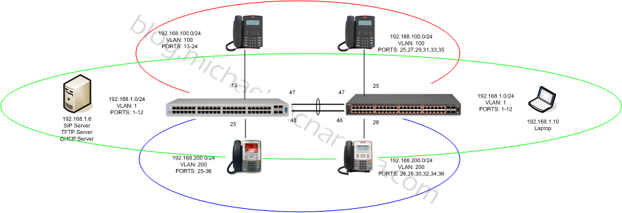
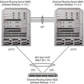
In my previous post I laid out the basics of how to configure multiple VLANs and enable IP routing on a stackable Avaya Ethernet Routing Switch. In this post I’m going to expand that topic to include trunking (802.1q) those VLANs to a second Ethernet Routing Switch. In this example I’ll add an Ethernet Routing Switch 4548 to the Ethernet Routing Switch 5520 that I had previously configured and deployed. We’ll create a Multi-Link Trunk between the two switches to bridge multiple VLANs across the 802.1q compliant link. Here’s a diagram of what the network should look like when we’re done;
In order to test I’ll move two of the IP phones to the Ethernet Routing Switch 4548 and I’ll use an old laptop to help verify the bridging.
Ethernet Routing Switch 4548
Let’s start with the Ethernet Routing Switch 4548GT-PWR and add the necessary configuration there first;
enable
config t
We start by creating VLAN 100 and VLAN 200 on the Ethernet Routing Switch 4548;
vlan create 100 name "192-168-100-0/24" type port
vlan members remove 1 25,27,29,31,33,35
vlan members add 100 25,27,29,31,33,35
vlan port 25,27,29,31,33,35 pvid 100

vlan create 200 name "192-168-200-0/24" type port
vlan members remove 1 26,28,30,32,34,36
vlan members add 200 26,28,30,32,34,36
vlan port 26,28,30,32,34,36 pvid 200
I’m not going to create a Layer 3 IP interfaces on these VLANs since the Ethernet Routing Switch 5520 is already routing for us. We just want to bridge the frames between the two switches not route them (not in this post anyway). Now let’s configure the ports that will make up the Mulit-Link Trunk;
vlan port 47,48 tagging TagAll
vlan members add 1 47,48
vlan members add 100 47,48
vlan members add 200 47,48
vlan port 47,48 pvid 1

mlt 1 disable
mlt 1 name "MLT_to_ERS5520"
mlt 1 learning disable
mlt 1 member 47,48
mlt 1 enable
That’s pretty much it. We enabled tagging on the uplink/downlink ports, added the necessary VLANs to the ports and then created and enabled a MLT.
Ethernet Routing Switch 4548 – Show Configuration
That should be the configuration for the Ethernet Routing Switch 4548… let’s just have a quick look at the VLANs;
4548GT-PWR(config)#show vlan
Id  Name                 Type     Protocol         User PID Active IVL/SVL Mgmt
--- -------------------- -------- ---------------- -------- ------ ------- ----
1   VLAN #1              Port     None             0x0000   Yes    IVL     Yes
        Port Members: 1-24,47-48
2   VLAN #2              Port     None             0x0000   Yes    IVL     No
        Port Members: 37-46
100 192-168-100-0/24     Port     None             0x0000   Yes    IVL     No
        Port Members: 25,27,29,31,33,35,47-48
200 192-168-200-0/24     Port     None             0x0000   Yes    IVL     No
        Port Members: 26,28,30,32,34,36,47-48
Total VLANs: 4
Let’s just check the Multi-Link Trunk configuration… if that’s wrong we could end up with a loop in the network;
4548GT-PWR(config)#show mlt 1
Id Name                 Members                Bpdu   Mode           Status
-- -------------------- ---------------------- ------ -------------- -------
1  MLT_to_ERS5520       47-48                  All    Basic          Enabled
You can see from the commands above that the ports are configured with the appropriate VLANs and the MLT is enabled.
Ethernet Routing Switch 5520
Let’s add the necessary configuration to the Ethernet Routing Switch 5520-PWR. I’m not going to repeat all the commands I performed in the yesterday’s post, instead I’ll just build upon the previous configuration adding what we need for the 802.1q trunking and the Multi-Link Trunking;
enable
config t
vlan port 47,48 tagging TagAll
vlan members add 1 47,48
vlan members add 100 47,48
vlan members add 200 47,48
vlan port 47,48 pvid 1

mlt 1 disable
mlt 1 name "MLT_to_ERS4548"
mlt 1 learning disable
mlt 1 member 47,48
mlt 1 enable
Ethernet Routing Switch 5520 – Show Configuration
That should be the configuration for the Ethernet Routing Switch 5520… let’s just have a quick look at the VLANs;
5520-48T-PWR#show vlan
Id  Name                 Type     Protocol         PID      Active IVL/SVL Mgmt
--- -------------------- -------- ---------------- -------- ------ ------- ----
1   test                 Port     None             0x0000   Yes    IVL     Yes
        Port Members: 1-12,37-48
100 192-168-100-0/24     Port     None             0x0000   Yes    IVL     No
        Port Members: 13-24,47-48
101 10-101-20-0/24       Port     None             0x0000   Yes    IVL     No
        Port Members: 25-36
200 192-168-200-0/24     Port     None             0x0000   Yes    IVL     No
        Port Members: 47-48
Total VLANs: 4
Let’s just check the Multi-Link Trunk configuration… if that’s wrong we could end up with a loop in the network;
5520-48T-PWR#show mlt 1
Id Name             Members                Bpdu   Mode           Status  Type
-- ---------------- ---------------------- ------ -------------- ------- ------
1  MLT_to_ERS4548   47-48                  All    Basic          Enabled Trunk
Since all stackable Avaya Ethernet Routing Switches support Auto-MDIX I can just use two regular CAT5e patch cables to connect the switches together. If the switches didn’t support Auto-MDIX I would need to use two crossover cables between them.
Ethernet Routing Switch 4548 – Operational Status
With link up on ports 47 and 48 I can check the following information. The topology table will show me the physical connections between the two switches. The MAC/FDB table will show me that there are multiple MAC/FDB entries in VLANs 100 and 200 being learned across “Trunk 1”. The LLDP table will show me the Avaya IP phones that I’ve connected to ports 25 and 26.
4548GT-PWR#show autotopology nmm-table
LSlot                                                                     RSlot
LPort IP Addr          Seg ID  MAC Addr     Chassis Type     BT LS   CS   RPort
----- --------------- -------- ------------ ---------------- -- --- ----  -----
0/ 0 192.168.1.25    0x000000 001E7E7C2C01 4548GT-PWR       12 Yes HTBT    NA
1/47 192.168.1.50    0x000130 001F0ACEBC01 5520-48T-PWR     12 Yes HTBT   1/48
1/48 192.168.1.50    0x00012f 001F0ACEBC01 5520-48T-PWR     12 Yes HTBT   1/47

4548GT-PWR#show mac-address-table
Mac Address Table Aging Time: 300
Number of addresses: 20

   MAC Address    Vid  Source         MAC Address    Vid  Source
----------------- ---- -------     ----------------- ---- -------
00-02-B3-CB-77-A2    1 Port:19     00-04-61-9E-46-7E    1 Port:21
00-0C-29-64-33-F9    1 Port:19     00-0C-29-A5-CB-54    1 Port:19
00-18-01-EA-F4-45    1 Port: 1     00-1C-11-6B-DC-6B    1 Port: 1
00-1C-11-6D-15-27    1 Port: 1     00-1C-11-6D-15-DC    1 Port: 1
00-1E-7E-7C-2C-00    1             00-1E-7E-7C-2C-40    1
00-1F-0A-CE-BC-40    1 Trunk:1     00-1F-D0-D0-BE-2D    1 Port:17
00-23-EE-96-AA-21    1 Port: 1     00-24-B5-F6-94-02    1 Trunk:1
00-0A-E4-76-9C-C8    2 Port:45     00-1F-0A-CE-BC-01    2 Trunk:1
00-24-DC-DF-0D-08    2 Port:43     00-A0-F8-5E-CE-BC    2 Port:39
00-1F-0A-CE-BC-41  100 Trunk:1     00-24-7F-99-84-70  100 Port:25
00-24-7F-99-84-E9  100 Trunk:1     00-1E-CA-F3-1D-B4  200 Port:26

4548GT-PWR#show lldp neighbor
-------------------------------------------------------------------------------
                            lldp neighbor
-------------------------------------------------------------------------------
Port: 26    Index: 4                  Time: 13 days, 22:42:31
        ChassisId: Network address    IPv4  192.168.200.5
        PortId:    MAC address        00:1e:ca:f3:1d:b4
        SysCap:    TB / TB            (Supported/Enabled)
        PortDesc:  Avaya IP Phone
        SysDescr:  Avaya IP Telephone 1120E, Firmware:SIP1120e04.00.04.00

-------------------------------------------------------------------------------
Port: 25    Index: 6                  Time: 13 days, 22:43:48
        ChassisId: Network address    IPv4  192.168.100.98
        PortId:    MAC address        00:24:7f:99:84:70
        SysCap:    TB / TB            (Supported/Enabled)
        PortDesc:  Avaya IP Phone
        SysDescr:  Avaya IP Telephone 1220, Firmware:SIP12x004.00.04.00

-------------------------------------------------------------------------------
Sys capability: O-Other; R-Repeater; B-Bridge; W-WLAN accesspoint; r-Router;
T-Telephone; D-DOCSIS cable device; S-Station only.
Total neighbors: 2
Ethernet Routing Switch 5520 – Operational Status
I can check all the same information on the ERS5520.. The topology table will show me the physical connections between the two switches. The MAC/FDB table will show me that there are multiple MAC/FDB entries in VLANs 100 and 200 being learned across “Trunk 1”. The LLDP table will show me the Avaya IP phones that I’ve connected to ports 13 and 25.
5520-48T-PWR#show autotopology nmm-table
LSlot                                                                     RSlot
LPort IP Addr          Seg ID  MAC Addr     Chassis Type     BT LS   CS   RPort
----- --------------- -------- ------------ ---------------- -- --- ----  -----
 0/ 0 192.168.1.50    0x000000 001F0ACEBC01 5520-48T-PWR     12 Yes TPCH    NA
 1/47 192.168.1.25    0x00012f 001E7E7C2C01 4548GT-PWR       12 Yes TPCH   1/47
 1/48 192.168.1.25    0x000130 001E7E7C2C01 4548GT-PWR       12 Yes TPCH   1/48

5520-48T-PWR#show mac-address-table
Mac Address Table Aging Time: 300
Number of addresses: 16

   MAC Address    Vid  Source         MAC Address    Vid  Source
----------------- ---- -------     ----------------- ---- -------
00-02-B3-CB-77-A2    1 Trunk:1     00-04-61-9E-46-7E    1 Trunk:1
00-0C-29-64-33-F9    1 Trunk:1     00-0C-29-A5-CB-54    1 Trunk:1
00-18-01-EA-F4-45    1 Trunk:1     00-1C-11-6B-DC-6B    1 Trunk:1
00-1C-11-6D-15-27    1 Trunk:1     00-1C-11-6D-15-DC    1 Trunk:1
00-1E-7E-7C-2C-01    1 Trunk:1     00-1E-7E-7C-2C-40    1 Trunk:1
00-1F-0A-CE-BC-00    1             00-1F-0A-CE-BC-40    1
00-1F-D0-D0-BE-2D    1 Trunk:1     00-23-EE-96-AA-21    1 Trunk:1
00-24-B5-F6-94-02    1 Port: 9     00-1F-0A-CE-BC-41  100
00-24-7F-99-84-70  100 Trunk:1     00-24-7F-99-84-E9  100 Port:15
00-1E-CA-F3-1D-B4  200 Trunk:1

5520-48T-PWR#show lldp neighbor
-------------------------------------------------------------------------------
                            lldp neighbor
-------------------------------------------------------------------------------
Port: 13     Index: 5                  Time: 0 days, 00:02:00
        ChassisId: Network address    IPv4  192.168.100.4
        PortId:    MAC address        00:24:b5:f6:94:02
        SysCap:    TB / TB            (Supported/Enabled)
        PortDesc:  Avaya IP Phone
        SysDescr:  Avaya IP Telephone 1165E, Firmware:SIP1165e04.00.04.00

-------------------------------------------------------------------------------
Port: 25    Index: 6                  Time: 0 days, 00:02:19
        ChassisId: Network address    IPv4  192.168.200.99
        PortId:    MAC address        00:24:7f:99:84:e9
        SysCap:    TB / TB            (Supported/Enabled)
        PortDesc:  Avaya IP Phone
        SysDescr:  Avaya IP Telephone 1220, Firmware:SIP12x004.00.04.00

-------------------------------------------------------------------------------
Sys capability: O-Other; R-Repeater; B-Bridge; W-WLAN accesspoint; r-Router;
T-Telephone; D-DOCSIS cable device; S-Station only.
Total neighbors: 2
Would you be interested in seeing a screencast of this whole process?
Let me know if you have any questions or would like to point out corrections!
Cheers!


