I don’t think this blog is that popular by any stretch of the imagination…
Juniper SSL VPN Secure Access 6.5 Available
Juniper recently released a new version of software for their SSL VPN (Secure Access) appliances. The new release is important because it finally addresses a problem that was original documented on my blog in this post. While I have yet to deploy this new software release (I would be interested in hearing from those that have) I thought it warranted a new post.
This latest version of software now supports Windows Secure Application Manager (WSAM) when used on Windows XP 64-bit and Windows Vista 64-bit clients. There was no mention of Windows 7 which is due to be released October 22, 2009. I did find it interesting that Internet Explorer 8 was only “compatible” with respect to a few of the features while Internet Explorer 7 was “qualified” with all features (review Juniper Secure Access 6.5 Supported Platforms document for specifics). I did a quick search over in the Juniper forums and found some reports that Host Checker wasn’t working properly with Windows 7 RC.
There were two new features that jumped out at me in the What’s New document;
RDP Launcher
SA 6.5 simplifies the use of RDP sessions for end users without requiring them or administrators to create bookmarks.
- Simplifies ease of use for remote users to RDP into remote desktops by merely clicking a button or entering a hostname or IP Address of the remote computer.
- Simplifies the configuration for administrators and reduces the number of support calls from users who are unable to figure out how to RDP to remote computers.
VDI Support
Secure Access (SA) version 6.5 interoperates with VDI products, including VMWare’s View Manager and Citrix’s XenDesktop, enabling administrators to deploy virtual desktops alongside the SA series of SSL VPN devices. This allows the SA administrator to configure centralized remote access policies for users who access their virtual desktops.
- This provides a centralized point of configuration for administrators to configure remote access policies for virtual desktop access through leading virtualization products from VMWare and Citrix.
- SA 6.5 provides end users the VDI client to access the virtual desktop through, and provides flexible client fallback options thereby simplifying the deployment and management for administrators.
We have a lot of folks looking to access their corporate desktops remotely and the RDP (Terminal Services) feature of the Juniper SSL VPN really helps fill that role.
Cheers!
References;
What’s New in Juniper Networks Secure Access (SA) SSL VPN Version 6.5
Juniper Secure Access 6.5 Release Notes
WSAM and Network Connect Error Messages Release 6.5
Juniper Secure Access 6.5 Support Platforms
Update: Thursday November 5, 2009
Let me get right to the point, I would not recommend anyone deploy 6.5R1 on their Juniper Secure Access appliances. There are known issues with the Juniper Windows Secure Application Manager (WSAM) and the following four security suites; Norton 360, Symantec AntiVirus, Zone Alarm Security, ESET NOD32. Users with Norton 360 could experience a blue screen of death (BSOD) using the Juniper Windows Secure Application Manager. Juniper has a hotfix available for 6.5R1 that resolves the BSOD issues with Norton 360. The hotfix is not generally available on the Juniper website so you must contact JTAC for the hotfix.
Additional information can be found at this post; http://blog.michaelfmcnamara.com/2009/10/norton-360-and-juniper-ssl-vpn-wsam/
Update: Friday September 19, 2009
A quick update… I’ve setup a spare SA4000 and received a demo license from Juniper to test the 6.5R1 software release (thanks Matt!). I’m happy to report that the upgrade on the appliance was very smooth although it took about 6 minutes for the appliance to boot back up giving me a few frightful thoughts. Unfortunately the same can’t be said of the client software. I’m still in the process of testing but it appears that non-Administrator users (users that don’t have Administrator rights on the PC) won’t be functional after the upgrade until an Administrator manually installs the latest and greatest Juniper Installer Service. The Juniper Installer Service is designed to allow the client software to upgrade when the user doesn’t have Administrator rights. Users with Administrator rights work fine so long as they answer the prompts to install the new version of the Juniper Installer Service. I hope to release a detailed post in the next few days including some testing of Windows Vista 64-bit desktops.
vSphere SCSI reservation conflict
We had our first issue today with our recent VMware vSphere 4 installation. We’re currently up to about 30 virtual machines spread across five BL460c (36GB) blades in an HP 7000 Enclosure. The problem started with a few virtual machines just going south, like they had lost their mind. It was discovered that all the virtual machines that were affected were on the same datastore (LUN). One of the engineers put the ESX host that was running those VMs into maintenance mode and rebooted it. After the reboot the ESX host was unable to mount the datastore. Everything seemed fine from a SAN standpoint and the Fiber Channel switches were working fine. A quick look at /var/log/vmkwarning on the ESX host revealed the following messages;
Sep 1 13:04:35 mdcc01h10r242 vmkernel: 0:00:26:02.384 cpu4:4119)WARNING: ScsiDeviceIO: 1374: I/O failed due to too many reservation conflicts. naa.600508b4000547cc0000b00001540000 (920 0 3) Sep 1 13:04:40 mdcc01h10r242 vmkernel: 0:00:26:07.400 cpu6:4119)WARNING: ScsiDeviceIO: 1374: I/O failed due to too many reservation conflicts. naa.600508b4000547cc0000b00001540000 (920 0 3) Sep 1 13:04:40 mdcc01h10r242 vmkernel: 0:00:26:07.400 cpu6:4119)WARNING: Partition: 705: Partition table read from device naa.600508b4000547cc0000b00001540000 failed: SCSI reservation conflict
A quick examination of the other ESX hosts revealed the following;
Sep 1 13:04:26 mdcc01h09r242 vmkernel: 21:22:13:25.727 cpu10:4124)WARNING: FS3: 6509: Reservation error: SCSI reservation conflict Sep 1 13:04:31 mdcc01h09r242 vmkernel: 21:22:13:30.715 cpu12:4124)WARNING: FS3: 6509: Reservation error: SCSI reservation conflict Sep 1 13:04:36 mdcc01h09r242 vmkernel: 21:22:13:35.761 cpu9:4124)WARNING: FS3: 6509: Reservation error: SCSI reservation conflict
We had a SCSI reservation issue that was locking out the LUN from any of the ESX hosts. The immediate suspect was the VCB host as it was the only other host that was being presented the same datastores (LUNs) as the ESX hosts from the SAN (HP EVA 6000).
We rebooted the VCB host and then issued the following command to reset the LUN from one of the ESX hosts;
vmkfstools -L lunreset /vmfs/devices/disks/naa.600508b4000547cc0000b00001540000
After issuing the LUN reset we observed the following message in the log;
Sep 1 13:04:40 mdcc01h10r242 vmkernel: 0:00:26:07.400 cpu9:4209)WARNING: NMP: nmp_DeviceTaskMgmt: Attempt to issue lun reset on device naa.600508b4000547cc0000b00001540000. This will clear any SCSI-2 reservations on the device.
The ESX hosts were almost immediately able to see the datastore and the problem was resolved.
We believe the problem occurred when the VCB host tried to backup multiple virtual machines from the same datastore (LUN) at the same time. This created an issue when the VCB host locked the LUN for too long causing the SCSI queue to fill-up on the ESX hosts. This is new to us and to me so we’re still trying to figure it out.
Cheers!
References;
http://kb.vmware.com/kb/1009899
http://www.vmware.com/files/pdf/vcb_best_practices.pdf
LACP Configuration Examples (Part 3)
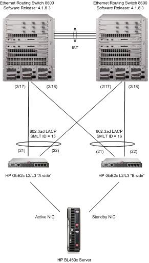
In part 3 of this series I’ll provide a relatively simple example of a LACP LAG between a HP GbE2c L2/L3 switch and two Nortel switches, we’ll terminate two different LAGs on the two ERS 8600 switches using Nortel’s proprietary SMLT (Split MultiLink Trunking) technology.
Example 2 – Ethernet Routing Switch 8600 to a set of HP GbE2c L2/L3 switches using LACP trunks with SMLT
As I said before a picture is worth a thousand words and can be very helpful in designing any network topology.
I’m going to skip the configuration of the two Nortel Ethernet Routing Switch 8600s since you can refer to the earlier post for an example of how to configure them. In this design we need to disable the virtual cross connect that exists between the A and B sides of the two HP GbE2c switches. Please note that I’m working with the HP GbE2c (C-Class enclosure) not the GbE2 (P-Class enclosure). There are some slight differences between the two. The virtual trunk ports between the A and B sides are on ports 17 and 18 so those ports need to be disabled in order to prevent a loop.
HP-GbE2c-A / HP-GbE2c-B /c/port 17/dis /c/port 18/dis
With the virtual trunk cross connects disabled we can now wire each switch independently to the upstream switch(s) which in this case happens to be two ERS 8600s. As is usual for me I’ll create a network management VLAN and place the IP interface of each GbE2c switch in that VLAN (VLAN 200).
HP-GbE2c-A / HP-GbE2c-B /c/l2/vlan 200 /c/l2/vlan 200/ena /c/l2/vlan 200/name "10-101-255-0/24"
Let’s add VLAN 200 to the two ports, 21 and 22, that we’ll be using to uplink to the 8600 switches. We haven’t yet enabled tagging so the switch will ask you if you’d like to change the PVID from VLAN 1 (default) to VLAN 200, you can safely answer yes to this question.
HP-GbE2c-A / HP-GbE2c-B /c/l2/vlan 200/add 21 /c/l2/vlan 200/add 22
Let’s enable tagging on both uplink ports along with RMON and set the PVID just to be safe;
HP-GbE2c-A / HP-GbE2c-B /c/port 21/tag ena /c/port 21/pvid 200 /c/port 21/rmon e /c/port 22/tag ena /c/port 22/pvid 200 /c/port 22/rmon e
Let’s turn off Spanning Tree on the uplinks, we only want Spanning Tree local to the switch since SMLT will take care of providing the loop free topology.
HP-GbE2c-A / HP-GbE2c-B /c/l2/stp 1/port 21/off /c/l2/stp 1/port 22/off
Now it’s time to configure LACP and create the LAG (Link Aggregation Group). We’ll using LACP key 50 but you could use any admin key (number) so long as both ports are configured with the same admin key.
HP-GbE2c-A / HP-GbE2c-B /c/l2/lacp/port 21/mode active /c/l2/lacp/port 21/adminkey 50 /c/l2/lacp/port 22/mode active /c/l2/lacp/port 22/adminkey 50
Here’s the special sauce that will work in combination with the NIC teaming software to fail over in the event of an upstream switch problem or an uplink problem where the GbE2c continues to function but there’s a problem upstream. This configuration will cause the GbE2c switch to disable (admin-down) the server switch ports in the event that the LACP group goes down. This will cause the NIC teaming configuration on the servers to fail-over to the standby NIC.
HP-GbE2c-A / HP-GbE2c-B /c/ufd/on /c/ufd/fdp/ltm/addkey 50 /c/ufd/fdp/ltd/addport 1 /c/ufd/fdp/ltd/addport 2 /c/ufd/fdp/ltd/addport 3 /c/ufd/fdp/ltd/addport 4 /c/ufd/fdp/ltd/addport 5 /c/ufd/fdp/ltd/addport 6 /c/ufd/fdp/ltd/addport 7 /c/ufd/fdp/ltd/addport 8 /c/ufd/fdp/ltd/addport 9 /c/ufd/fdp/ltd/addport 10 /c/ufd/fdp/ltd/addport 11 /c/ufd/fdp/ltd/addport 12 /c/ufd/fdp/ltd/addport 13 /c/ufd/fdp/ltd/addport 14 /c/ufd/fdp/ltd/addport 15 /c/ufd/fdp/ltd/addport 16
If you haven’t already let’s configure an IP address (for management) on VLAN 200;
HP-GbE2c-A /c/l3/if 1/ena /c/l3/if 1/addr 10.1.255.128 /c/l3/if 1/mask 255.255.255.0 /c/l3/if 1/broad 10.1.255.255 /c/l3/if 1/vlan 200
We need to use a different IP address for the B side switch on VLAN 200;
HP-GbE2c-B /c/l3/if 1/ena /c/l3/if 1/addr 10.1.255.129 /c/l3/if 1/mask 255.255.255.0 /c/l3/if 1/broad 10.1.255.255 /c/l3/if 1/vlan 200
As mentioned by a few other folks on this blog and in the forums this solution only provides an active/passive solution in terms of the NIC teaming configuration. This is because the GbE2c L2/L3 switches don’t support IST/SMLT technology. While this will only provide 1Gbps of bandwidth (2Gbps if you count full duplex) between the blade server and the network it will provide significant level of redundancy and high-availability. In this design the network is protected from a GbE2c switch failure, a Nortel Ethernet Routing Switch 8600 failure, and multiple uplink/downlink failures.
Please feel free to post comments and questions here about this post. Questions regarding specific configurations can be posted in the forums; http://forums.networkinfrastructure.info/nortel-ethernet-switching/
Cheers!
LACP Configuration Examples (Part 2)
[ad name=”ad-articlebodysq”]In part 1 of this post I provided a pretty simple example of an LACP LAG between two Nortel switches. In this post I’ll provide another example with a small twist thrown in; we’ll terminate the LAG on two ERS 8600 switches using Nortel’s proprietary SMLT (Split MultiLink Trunking) technology. In this example I’ll substitute the Nortel Ethernet Switch 470 for a Ethernet Routing Switch 5520. You’ll notice that the LACP configurations (commands) are identical between the 470 and 5520 switches.
Example 2 – Ethernet Routing Switch 8600 to Ethernet Switch 5520 using LACP trunk with SMLT
As I said before a picture is worth a thousand words and can be very helpful in designing any network topology.
As with the previous example we’ll start with the Ethernet Routing Switch 8600s and then progress to the Ethernet Routing Switch 5520s. In this example we’ll need to configure two ERS 8600 switches, I’ll assume that you already have an IST (InnerSwitch Trunk) built and running properly.
Let’s start by configuring a MLT group the same way we did so in the previous example. The ERS8600-A switch first;
ERS8600-A config mlt 15 create config mlt 15 name "SMLT_LACP" config mlt 15 lacp key 15 config mlt 15 lacp enable
Now the ERS8600-B switch;
ERS8600-B config mlt 15 create config mlt 15 name "SMLT_LACP" config mlt 15 lacp key 15 config mlt 15 lacp enable
In this example I’ve chosen to connect the uplinks to port 2/17 on each switch. I’ve chosen to use the same ports on both switches only to make the configuration easier to understand for myself. I would use whatever ports I wanted on either switch so long as they are all running at the same speed. In this case the ports are both 10/100Mbps ports and will auto-negotiate to 100Mbps with the MDI-X feature of the ERS 5520 switch.
I’ll enable tagging (802.1q) just like I did in my previous example and I’ll remove VLAN 1 and add VLAN 99. Outside of this example you would just add whatever VLANs you’ll be extended to the edge switch.
ERS8600-A config ethernet 2/17 perform-tagging enable config vlan 1 ports remove 2/17 config vlan 99 ports add 2/17
Now the ERS8600-B switch;
ERS8600-B config ethernet 2/17 perform-tagging enable config vlan 1 ports remove 2/17 config vlan 99 ports add 2/17
Next we’ll enable LACP on the specific ports and group them using the same admin key;
ERS8600-A config ethernet 2/17 lacp key 15 config ethernet 2/17 lacp aggregation true config ethernet 2/17 lacp timeout short config ethernet 2/17 lacp enable
Now the ERS8600-B switch;
ERS8600-B config ethernet 2/17 lacp key 15 config ethernet 2/17 lacp aggregation true config ethernet 2/17 lacp timeout short config ethernet 2/17 lacp enable
Now because we’re going to be running in an SMLT configuration we need to make a few global changes. We need to enable LACP globally, but we also need to make sure that both switches use the same LACP identifier when communicating with the edge switch. This is necessary so the edge switch won’t know that it’s actually connected to two different switches upstream. If the LACP identifiers didn’t match between the two ERS8600 switches the edge switch would become confused.
ERS8600-A config lacp smlt-sys-id 00:01:81:28:84:00 config lacp enable
Now the ERS8600-B switch;
ERS8600-B config lacp smlt-sys-id 00:01:81:28:84:00 config lacp enable
We need to configure the MLT to operate in an SMLT configuration. We also need to make sure that any VLANs we are extending to the edge switch are also bridged across the IST between the two ERS 8600 switches. In this example I’m extending VLAN 99 so I need to add VLAN 99 to the IST which happens to be MLT 1.
ERS8600-A config mlt 15 smlt create smlt-id 15 config vlan 99 add-mlt 1
Now the ERS8600-B switch;
ERS8600-B config mlt 15 smlt create smlt-id 15 config vlan 99 add-mlt 1
That’s all the commands required for the two ERS8600 switches.
With that said there are some best practices that should be applied to all downlinks when utilizing SMLT.
While I left this out of the previous example these settings are applicable to both examples.
Let’s make sure that we enable CP-LIMIT which will shutdown the port if the switch receives too many broadcast or multicast frames per second. While some users don’t like this feature it’s better to cut off an offending closet than loose an entire network due to a loop or misconfigured switch. A word of warning here! You do not want CP-LIMIT enabled on any ports used in your IST, you also don’t want it enabled on the uplinks of any ERS8600 switches that reside at the edge as they might cut themselves off from the network. Instead enable it in the core on the downlinks to the edge switches and closet switches.
ERS8600-A config ethernet 2/17 cp-limit enable multicast-limit 2500 broadcast-limit 2500
Now the ERS8600-B switch;
ERS8600-B config ethernet 2/17 cp-limit enable multicast-limit 2500 broadcast-limit 2500
Another feature that helps protect the network is SLPP (Simple Loop Protection Protocol). In my opinion this feature is a must for any serious network. I can’t tell you how many times this feature has saved the networks I manage today. This feature will detect a misconfigured MLT/LACP at the edge switch and shutdown one of the downlink ports to preventing a loop. With SLPP you need to pay attention to the threshold setting. You want different thresholds between the two ERS8600 switches so that only one uplink gets shutdown.
ERS8600-A config slpp add 99 config slpp operation enable config ethernet 2/17 slpp packet-rx-threshold 50 config ethernet 2/17 slpp packet-rx enable
Now the ERS8600-B switch with a threshold of 5;
ERS8600-B config slpp add 99 config slpp operation enable config ethernet 2/17 slpp packet-rx-threshold 5 config ethernet 2/17 slpp packet-rx enable
That’s it for the two ERS8600 switches.
I’m literally going to cut and past the configuration of the ERS5520 from the previous example as it should be identical.
vlan ports 33,34 tagging tagAll
Let’s add VLAN 99 to the ports, I’ve already created the VLAN ahead of time.
vlan members add 99 33,34
Now we just need to configure the LACP parameters for each port and then enable LACP.
interface fastEthernet 33-34 lacp key 13 lacp mode active lacp timeout-time short lacp aggregation enable exit
Hopefully that’s been helpful!
Cheers!
- « Previous Page
- 1
- …
- 111
- 112
- 113
- 114
- 115
- …
- 151
- Next Page »