One of the most popular blog posts I’ve written in the past five years is, VLANs and IP Routing on an Ethernet Routing Switch. It continues to be the top post on my blog so I decided to write a follow-up using Cisco equipment. This has been covered many times on the Internet before but I’m going to try and add my spin to it here. In this example I’m going to take a Cisco 1921 router and a Cisco 3560-CX switch and show two different examples of how you could design a simple topology.
Example 1 – VLAN Routing on Router (Layer 2 Switching)
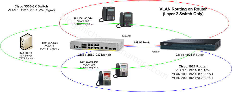
In the old days when we only had Layer 2 switching we could create an 802.1Q/ISL trunk between the switch and the router and we would route from the physical router itself. The switch would have an IP address just for management and was generally incapable of routing traffic. The router would have the IP address for every VLAN and that would be the default gateway for every device in that specific VLAN. If there is no WAN or Internet link this topology is often referred to as a router on a stick. The topology might look something like this;

This was and still is a widely accepted design although it has significant limitations since the legacy Cisco router is generally not capable of wire speed routing. In the case of the Cisco 1921 it can handle anywhere from 68Mbps – 110Mbps depending on packet size and configured features. Lots of people upgrade their Layer 2 switches to Gigabit only to later figure out that they can’t achieve Gigabit speeds between VLANs because they are routing between VLANs on a legacy software based router.
Example 2 – VLAN Routing on Switch (Layer 3 Switching)
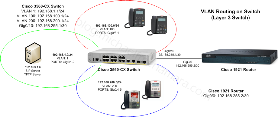
The newer accepted design is to do Layer 3 switching (routing) right on the switch itself, no need to include the legacy router. The IP interface for each VLAN is moved to the actual switch and traffic between those VLANs doesn’t need to leave the physical switch. That topology might look something like this;

In this design all the internal routing occurs on the Cisco 3560 which is capable or wire speed switching and routing thanks to the ASIC hardware. In this case we can now achieve near Gigabit transfer speeds between the VLANs, the only real variable is the speed of the actual source and destination device – servers, laptops, desktops, etc. We isolate the WAN router so it’s only required when we need to communicate with the WAN or Internet. We might only have a 50Mbps Internet connection so the legacy router is capable of handling that amount of traffic and provides additional features such as NAT for hiding our private network from the public Internet.
So what’s the configuration look like, it’s actually pretty straight forward;
Example 1 – Cisco 3560-CX Switch
enable
config t

username mike privilege 15 secret mypassword
enable secret myenable

vlan 100
 name "VLAN_100"
vlan 200
 name "VLAN_200"

inter vlan 1
 ip address 192.168.1.10 255.255.255.0
 no shut

inter range gig0/1-2
 switchport mode access
 switchport access vlan 1
inter range gig0/3-4
 switchport mode access
 switchport access vlan 100
inter range gig0/5-6
 switchport mode access
 switchport access vlan 200
inter gig0/10
 switchport mode trunk

line vty 0 4
 login local
Example 1 – Cisco 1921 Router
enable
config t

username mike privilege 15 secret mypassword
enable secret myenable

inter gig0/0.1
encapsulation dot1q 1
ip address 192.168.1.1 255.255.255.0
description VLAN_1
exit

inter gig0/0.100
encapsulation dot1q 100
ip address 192.168.100.1 255.255.255.0
description VLAN_100
exit

inter gig0/0.200
encapsulation dot1q 200
ip address 192.168.200.1 255.255.255.0
description VLAN_200
exit

line vty 0 4
 login local
Let’s look at the commands needed for the second example. In this case you’ll notice that I added a few IP routes to the configuration. In this case I added a default route on the Cisco 3560 forwarding traffic to the Cisco 2921. I also added IP routes to the Cisco 2921 for the IP subnets that we configured on the Cisco 3560. It’s not enough that the network knows where to send traffic to the destination. The network also needs to know how to send the replies back to the source devices, so we need routes in both directions.
Example 2 – Cisco 3560-CX Switch
enable
config t

username mike privilege 15 secret mypassword
enable secret myenable

vlan 100
 name "VLAN_100"
vlan 200
 name "VLAN_200"

inter vlan 1
 ip address 192.168.1.1 255.255.255.0
 no shut

inter vlan 100
 ip address 192.168.100.1 255.255.255.0
 no shut

inter vlan 200
 ip address 192.168.200.1 255.255.255.0


inter range gig0/1-2
 switchport mode access
 switchport access vlan 1
inter range gig0/3-4
 switchport mode access
 switchport access vlan 100
inter range gig0/5-6
 switchport mode access
 switchport access vlan 200

inter gig0/10
 desc UPLINK_C1921
 no switchport
 ip address 192.168.255.1 255.255.255.252
 no shut

ip route 0.0.0.0 0.0.0.0 192.168.255.2

line vty 0 4
 login local
Example 2 – Cisco 1921 Router
enable
config t

username mike privilege 15 secret mypassword
enable secret myenable

inter gig0/0
 descr UPLINK_C3560
 ip address 192.168.255.2 255.255.255.0
 exit

ip route 192.168.1.0 255.255.255.0 192.168.255.1
ip route 192.168.100.0 255.255.255.0 192.168.255.1
ip route 192.168.200.0 255.255.255.0 192.168.255.1

line vty 0 4
 login local
Cheers!
Note: Thanks to Cisco for providing the equipment I’m using today, it’s a small switch and router but it’s really helpful when working through example topologies to work on real equipment.