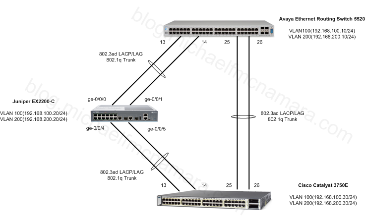
Let’s keep going… let’s bring a Cisco 3750E into the topology and let’s talk about utilizing Spanning Tree. Let’s get this out the way, Avaya does NOT recommend that you disable Spanning Tree. Avaya’s Split MultiLink Trunking (SMLT) is not compatible with the Spanning Tree Protocol so you can’t run STP over SMLT links. You can still run STP on edge ports and even ports utilizing MultiLink Trunking (MLT) or LACP/802.3ad. This is in contrast to Cisco’s Virtual Port Channel (vPC) which is interoperable with Spanning Tree.
Let’s look at expanding the topology from our last post adding a Cisco 3750E;
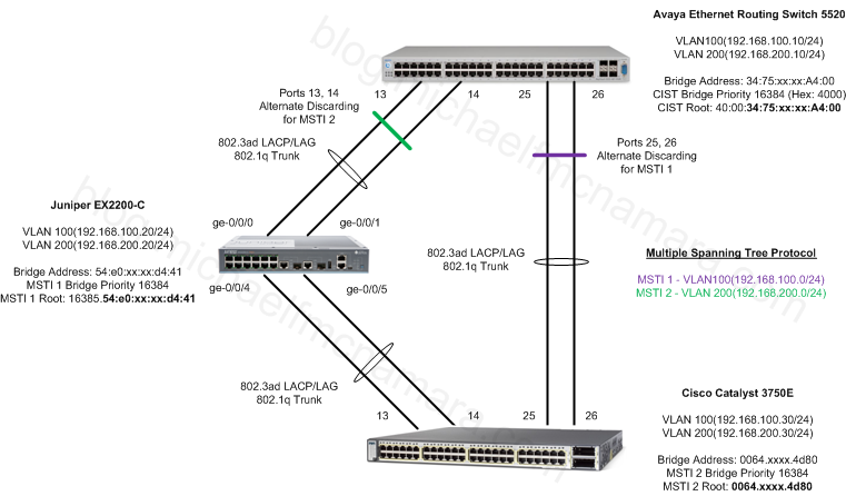
 Again, that’s pretty straight forward and isn’t too exciting. Although if we leave every uplink/downlink as a member of VLAN 100 and VLAN 200 we’ll end up with a loop in our topology – not a Spanning Tree Loop. What if we add Multiple Spanning Tree Protocol (MSTP) to our configuration just to make it interesting? Our topology might look like this with 2 instances of MSTP running, one for each VLAN.
We’ll make the Avaya switch the root bridge for CIST. We’ll make the Juniper switch the root bridge for MST 1, and we’ll make the Cisco switch the root bridge for MST 2.
That’s interesting… let’s see what we need to-do in order to configure everything up. I’m going to pickup the configuration as I had it setup in the previous post, LACP Configuration Examples (Part 4). We’ll need to add another LACP group/pair to our Avaya and Juniper switches as well as configure the Cisco switch. We’ll also need to enable MSTP on each switch, add the VLANs to the correct MSTP instances and set the correct bridge priority for each.
Juniper EX2200-C Switch
configure
set chassis aggregated-devices ethernet device-count 2

delete interfaces ge-0/0/4 unit 0
delete interfaces ge-0/0/5 unit 0

set interfaces ge-0/0/4 ether-options 802.3ad ae1
set interfaces ge-0/0/5 ether-options 802.3ad ae1
set interfaces ae1 aggregated-ether-options lacp active
set interfaces ae1 aggregated-ether-options lacp periodic fast

set interfaces ae1 unit 0 family ethernet-switching
set interfaces ae1 unit 0 family ethernet-switching port-mode trunk
set interfaces ae1 unit 0 family ethernet-switching port-mode trunk vlan members VLAN-100 members VLAN-200

delete protocols rstp

set protocols mstp configuration-name AcmeNetworks
set protocols mstp revision-level 1
set protocols mstp msti 1 vlan 100
set protocols mstp msti 2 vlan 200

set protocols mstp msti 1 bridge-priority 16384
commit and-quit
Avaya Ethernet Routing Switch 5520
config t
spanning-tree mode mst
exit
boot
You’ll need to reboot the switch in order to enable MSTP, so go ahead and reboot before continuing the steps;
config t
vlan ports 25,26 tagging tagAll

interface fastEthernet 25,26
lacp key 25
lacp mode active
lacp timeout-time short
lacp aggregation enable
exit

spanning-tree mstp msti 1
spanning-tree mstp msti 1 add-vlan 100
spanning-tree mstp msti 2
spanning-tree mstp msti 2 add-vlan 200
spanning-tree mstp priority 4000
You’ll notice that the Avaya switch accepts a hexadecimal value for the priority, so 4000 in hex = 16384 in decimal.
spanning-tree mstp region region-name AcmeNetworks
spanning-tree mstp region region-version 1
exit
Cisco Catalyst 3750E Switch
config t
vlan 100
name "192-168-100-0/24"
exit
vlan 200
name "192-168-200-0/24"
exit

interface vlan 100
ip address 192.168.100.30 255.255.255.0
no shut
exit

interface vlan 200
ip address 192.168.200.30 255.255.255.0
no shut
exit

interface gig1/0/13
switchport trunk encapsulation dot1q
switchport mode trunk
channel-protocol lacp
channel-group 1 mode active

interface gig1/0/14
switchport trunk encapsulation dot1q
switchport mode trunk
channel-protocol lacp
channel-group 1 mode active

interface gig1/0/25
switchport trunk encapsulation dot1q
switchport mode trunk
channel-protocol lacp
channel-group 2 mode active

interface gig1/0/26
switchport trunk encapsulation dot1q
switchport mode trunk
channel-protocol lacp
channel-group 2 mode active

spanning-tree mode mst

spanning-tree mst configuration
name AcmeNetworks
revision 1
instance 1 vlan 100
instance 2 vlan 200
exit
spanning-tree mst 2 priority 16384
exit
Let’s have a look at our work and see what everything looks like from both a LACP and Spanning Tree perspective.
Cisco Catalyst 3750E Switch
Switch#show lacp neighbor
Flags: S - Device is requesting Slow LACPDUs
F - Device is requesting Fast LACPDUs
A - Device is in Active mode P - Device is in Passive mode

Channel group 1 neighbors

Partner's information:

LACP port Admin Oper Port Port
Port Flags Priority Dev ID Age key Key Number State
Gi1/0/13 FA 127 54e0.xxxx.d440 5s 0x0 0x2 0x3 0x3F
Gi1/0/14 FA 127 54e0.xxxx.d440 5s 0x0 0x2 0x4 0x3F

Channel group 2 neighbors

Partner's information:

LACP port Admin Oper Port Port
Port Flags Priority Dev ID Age key Key Number State
Gi1/0/25 FA 32768 3475.xxxx.a400 14s 0x0 0x3019 0x19 0x3F
Gi1/0/26 FA 32768 3475.xxxx.a400 16s 0x0 0x3019 0x1A 0x3F

Switch#show spanning-tree

MST0
Spanning tree enabled protocol mstp
Root ID Priority 16384
Address 3475.xxxx.a400
Cost 0
Port 496 (Port-channel2)
Hello Time 2 sec Max Age 20 sec Forward Delay 15 sec

Bridge ID Priority 32768 (priority 32768 sys-id-ext 0)
Address 0064.xxxx.4d80
Hello Time 2 sec Max Age 20 sec Forward Delay 15 sec

Interface Role Sts Cost Prio.Nbr Type
------------------- ---- --- --------- -------- --------------------------------
Po1 Desg FWD 10000 128.488 P2p
Po2 Root FWD 10000 128.496 P2p

MST1
Spanning tree enabled protocol mstp
Root ID Priority 16385
Address 54e0.322a.d441
Cost 10000
Port 488 (Port-channel1)
Hello Time 2 sec Max Age 20 sec Forward Delay 15 sec

Bridge ID Priority 32769 (priority 32768 sys-id-ext 1)
Address 0064.xxxx.4d80
Hello Time 2 sec Max Age 20 sec Forward Delay 15 sec

Interface Role Sts Cost Prio.Nbr Type
------------------- ---- --- --------- -------- --------------------------------
Po1 Root FWD 10000 128.488 P2p
Po2 Desg FWD 10000 128.496 P2p

MST2
Spanning tree enabled protocol mstp
Root ID Priority 16386
Address 0064.xxxx.4d80
This bridge is the root
Hello Time 2 sec Max Age 20 sec Forward Delay 15 sec

Bridge ID Priority 16386 (priority 16384 sys-id-ext 2)
Address 0064.xxxx.4d80
Hello Time 2 sec Max Age 20 sec Forward Delay 15 sec

Interface Role Sts Cost Prio.Nbr Type
------------------- ---- --- --------- -------- --------------------------------
Po1 Desg FWD 10000 128.488 P2p
Po2 Desg FWD 10000 128.496 P2p
We can see that LACP is up and running to both the Avaya and Juniper switches. We can also see that the Cisco switch is the root bridge for MSTI 2 and the root port for MSTI 1 is Port-channel 1 (link to Juniper EX2200-C) while the root port for the CIST is Port-channel2 (link to Avaya ERS 5520). All ports are designated and forwarding traffic.
Juniper EX2200-C Switch
root> show lacp interfaces
Aggregated interface: ae0
LACP state: Role Exp Def Dist Col Syn Aggr Timeout Activity
ge-0/0/0 Actor No No Yes Yes Yes Yes Fast Active
ge-0/0/0 Partner No No Yes Yes Yes Yes Fast Active
ge-0/0/1 Actor No No Yes Yes Yes Yes Fast Active
ge-0/0/1 Partner No No Yes Yes Yes Yes Fast Active
LACP protocol: Receive State Transmit State Mux State
ge-0/0/0 Current Fast periodic Collecting distributing
ge-0/0/1 Current Fast periodic Collecting distributing

Aggregated interface: ae1
LACP state: Role Exp Def Dist Col Syn Aggr Timeout Activity
ge-0/0/4 Actor No No Yes Yes Yes Yes Fast Active
ge-0/0/4 Partner No No Yes Yes Yes Yes Slow Active
ge-0/0/5 Actor No No Yes Yes Yes Yes Fast Active
ge-0/0/5 Partner No No Yes Yes Yes Yes Slow Active
LACP protocol: Receive State Transmit State Mux State
ge-0/0/4 Current Slow periodic Collecting distributing
ge-0/0/5 Current Slow periodic Collecting distributing

root> show spanning-tree bridge

STP bridge parameters
Context ID : 0
Enabled protocol : MSTP

STP bridge parameters for CIST
Root ID : 16384.34:75:xx:xx:a4:00
Root cost : 0
Root port : ae0.0
CIST regional root : 16384.34:75:xx:xx:a4:00
CIST internal root cost : 10000
Hello time : 2 seconds
Maximum age : 20 seconds
Forward delay : 15 seconds
Hop count : 19
Message age : 0
Number of topology changes : 2
Time since last topology change : 14690 seconds
Topology change initiator : ae0.0
Topology change last recvd. from : 34:75:xx:xx:a4:01
Local parameters
Bridge ID : 32768.54:e0:xx:xx:d4:41
Extended system ID : 0
Internal instance ID : 0

STP bridge parameters for MSTI 1
MSTI regional root : 16385.54:e0:xx:xx:d4:41
Hello time : 2 seconds
Maximum age : 20 seconds
Forward delay : 15 seconds
Number of topology changes : 5
Topology change initiator : ae1.0
Topology change last recvd. from : 00:64:xx:xx:4d:8d
Local parameters
Bridge ID : 16385.54:e0:xx:xx:d4:41
Extended system ID : 0
Internal instance ID : 1

STP bridge parameters for MSTI 2
MSTI regional root : 16386.00:64:xx:xx:4d:80
Root cost : 10000
Root port : ae1.0
Hello time : 2 seconds
Maximum age : 20 seconds
Forward delay : 15 seconds
Hop count : 19
Number of topology changes : 6
Topology change initiator : ae1.0
Topology change last recvd. from : 00:64:xx:xx:4d:8d
Local parameters
Bridge ID : 32770.54:e0:xx:xx:d4:41
Extended system ID : 0
Internal instance ID : 2
Avaya Ethernet Routing Switch 5520
5520-48T-PWR#show lacp port 13-14,25-26
Admin Oper Trunk Partner
Port Priority Lacp A/I Timeout Key Key AggrId Id Port Status
---- -------- ------- --- ------- ----- ----- ------ ----- ------- ------
13 32768 Active A Short 1 12289 8224 32 1 Active
14 32768 Active A Short 1 12289 8224 32 2 Active
25 32768 Active A Short 25 12313 8223 31 282 Active
26 32768 Active A Short 25 12313 8223 31 283 Active

5520-48T-PWR#show spanning-tree mstp config
Maximum Mst Instance Number: 8
Number of Msti Supported: 2
Cist Bridge Priority (hex): 4000
Stp Version: Mstp Mode
Cist Bridge Max Age: 20 seconds
Cist Bridge Forward Delay: 15 seconds
Tx Hold Count: 3
Path Cost Default Type: 32-bit
Max Hop Count: 2000

VLAN members
------ ------ ------ ------ ------ ------ ------ ------ ------ ------
1

Msti Config Id Selector: 0
Msti Region Name: AcmeNetworks
Msti Region Version: 1
Msti Config Digest: 6D:A4:B5:0C:4F:D5:87:75:7E:EF:03:56:75:36:05:E1

5520-48T-PWR#show spanning-tree mstp msti config 1
Msti Bridge Regional Root:  40:00:54:E0:xx:xx:D4:41
Msti Bridge Priority (hex): F000
Msti Root Cost:             10000
Msti Root Port:             MLT 32
Msti State:                 Enabled

VLAN members
------ ------ ------ ------ ------ ------ ------ ------ ------ ------
100

5520-48T-PWR#show spanning-tree mstp msti config 2
Msti Bridge Regional Root:  40:00:00:64:xx:xx:4D:80
Msti Bridge Priority (hex): F000
Msti Root Cost:             10000
Msti Root Port:             MLT 31
Msti State:                 Enabled

VLAN members
------ ------ ------ ------ ------ ------ ------ ------ ------ ------
200

5520-48T-PWR#show spanning-tree mstp msti port role 1
Port Role State STP Status Oper Status
---- ---------- ---------- ---------- -----------
13 Root Forwarding Enabled Enabled
14 Root Forwarding Enabled Enabled
25 Alternate Discarding  Enabled Enabled
26 Alternate Discarding  Enabled Enabled

5520-48T-PWR#show spanning-tree mstp msti port role 2
Port Role State STP Status Oper Status
---- ---------- ---------- ---------- -----------
13 Alternate Discarding  Enabled Enabled
14 Alternate Discarding  Enabled Enabled
25 Root Forwarding Enabled Enabled
26 Root Forwarding Enabled Enabled
We can see from the output above that ports 13,14 are Alternate Discarding for MSTI 1 while ports 25,26 are Alternate Discarding for MSTI 2.
In the output we can see which port is the root bridge port for each switch, we can also see the MSTP config digest which should match on every switch in the topology. In order for the configuration to be valid the MST region name, version and config selector need to match along with correct VLAN IDs matched to the correct MST instance.
Cheers!
Image Credit: New York City Brooklyn Bridge by Diogo Ferrari
